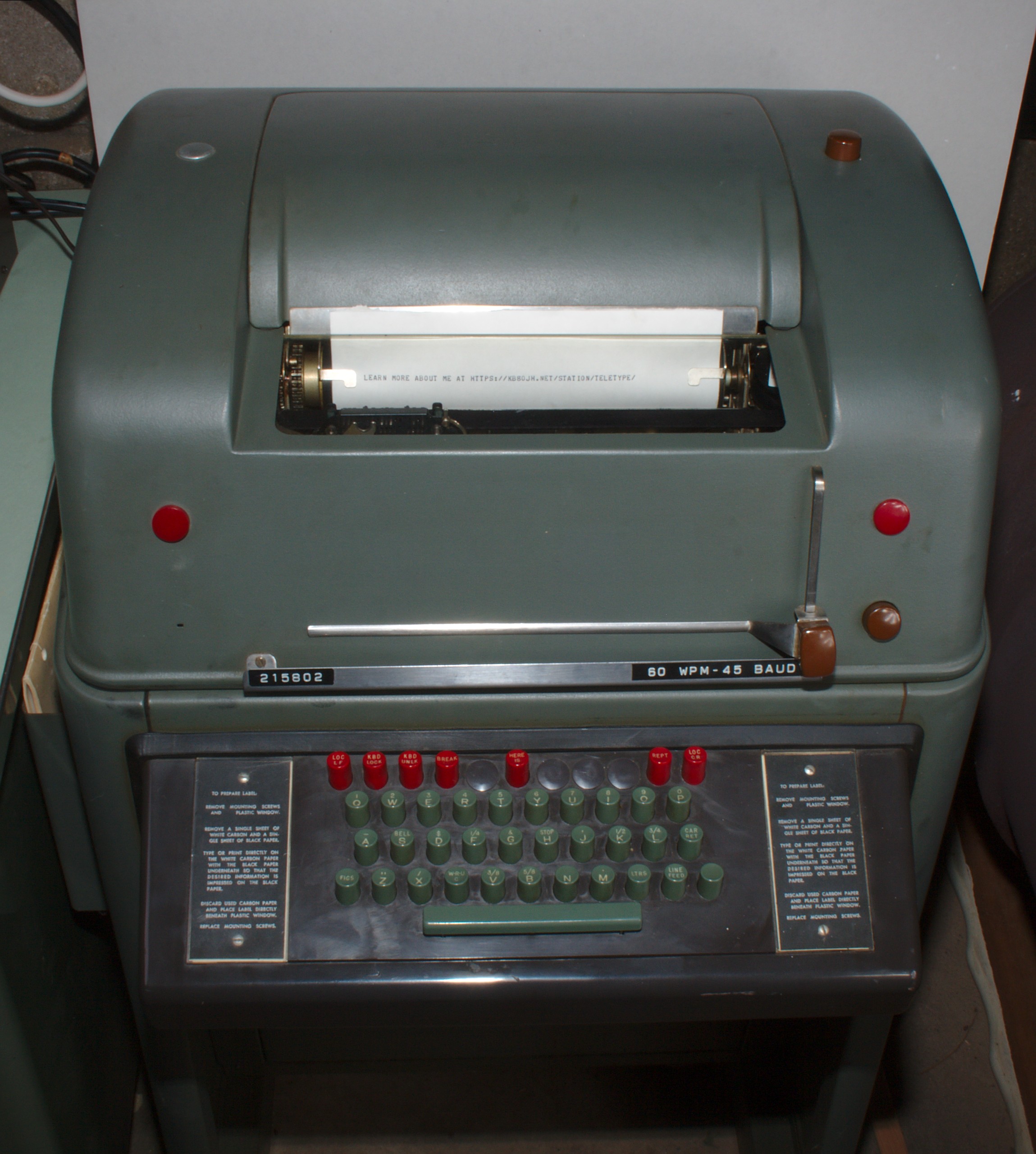
Teletype Model 28 KSR
I have always been interested in Teletype machines, both as mechanical marvels and for their place in communication and computing history. Bill Strangfeld, W8FIX, found a Teletype Model 28 KSR (a 5-bit Baudot-encoded keyboard and teleprinter operating at 45.45 baud, which is the standard for Amateur RTTY) for me and I have paired it with my vintage station for digital communication. Here I will describe the machine, provide some photos, and pass along some of the things I have discovered about its operation and maintenance.
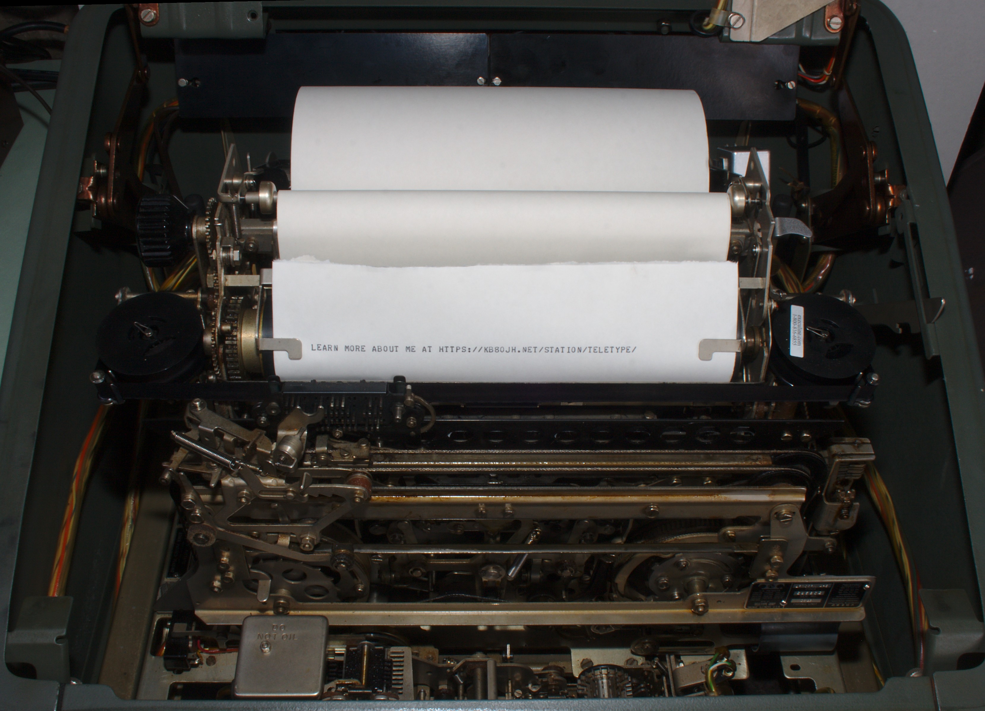
As a point of interest, the URL banner across the top of this page was printed on my Teletype onto 2-ply carbonless copy paper, scanned, and the background cleared (to remove paper texture) in the GIMP. No other editing was performed, that’s what the Teletype font and print looks like. I particularly like the curved stems on the H and N (M, which does not appear in the banner text, is similar) and the hooked serifs. Registration of Model 28 Teletype text appears to be much better than I am used to seeing with mechanical typewriters, I assume due to the precision with which the type box is placed.
Note: My YouTube channel contains a series of videos about my Teletype equipment that you might find interesting!
My Teletype
The unit itself. Note the manual box on the left-hand side with a HAL terminal manual sticking out!
The particular Teletype I have is a console Model 28 KSR (Keyboard Send Receive) that appears to have originally been purchased as a TWX terminal, the Bell response to the then-European Telex service. It has a keyboard laid out for the TWX character set and the model numbers of all of the components I have been able to identify (keyboard unit, typing unit, and cabinet) are models issued specifically for TWX use. As I understand it, this means that it would have originally been geared for 100 WPM service, while Amateur RTTY is 60 WPM. In addition, it would have originally had a typing box with the “wrong” character set. Both of these have been converted to configurations appropriate for Amateur service prior to my receipt of the unit.
An interesting feature of TWX teletypes is a self-identifier mechanism that is triggered by a red button on the keyboard labeled “Here Is”. Pressing this button causes a rotary drum with Baudot-encoded sheet metal keys on it to spin out an identifying sequence. The Teletype I have spins out “GTM CDRVILLE”, which at this point I am assuming means Cedarville, OH (due to the fact that it was acquired from SW Ohio). I hope to have unencoded keys for this wheel fabricated so that I can use it to spin out my call sign at one touch.
The Model 28
The Model 28 “Teletype” (as opposed to other Teletype equipment in the Model 28 series, such as tape readers and reperforators) was available in a number of configurations. The KSR configuration consists of a keyboard sending unit and a page printer receiving unit in the same cabinet. The cabinet can be console (floor standing), wall mounted, or desktop. There was also an ASR (Automatic Send Receive) configuration which combined the functionality of a KSR with a tape reader and writer, a KTR configuration that consists of a keyboard married to a tape reperforator, a RO (Receive-Only) configuration that had a page printer but no keyboard unit, and several others.
Each Model 28 KSR has five major components: the keyboard unit, typing unit, electrical service unit (LESU), motor unit, and cabinet. In order of increasing complexity, these are:
- Cabinet: Every Model 28 cabinet contains terminal blocks for wiring together the various units (except for some complicated cables connecting the LESU to the typing and keyboard units), the power input and loop cables, and support structures for the keyboard/typing units. The console KSR cabinet also has a signal bell, margin indicator lamp, copy illumination lamps, and a shallow 19" rack underneath, while the ASR cabinet includes these features plus mounting locations for the tape processing units it may contain.
- Motor Unit: The motor mounts on a sub-chassis that bolts to the keyboard unit, and contains the synchronous motor itself and a starting relay and capacitor. There is also a governed motor unit available.
- Electrical Service Unit: Nearly always referred to as the LESU to save space, this contains the power source interface (e.g., fuse holder and “convenience outlet” for mains operation), wiring harnesses that connect the typing and keyboard units, and optionally a number of electrical modules such as a polar relay interface to the incoming signal line, a local loop supply for the typing and keyboard interfaces, etc.
- Keyboard Unit Mounting the motor unit and typing unit, the Keyboard Unit is the true base of a 28 KSR — while the cabinet supports it all (on a rubber-mounted frame, no less!), the keyboard unit aligns the various drive shafts and transfers some signals back and forth between units. Itself, it includes the keyboard keys and their operating levers, a signal encoder for transforming key presses into Baudot, and, on the TWX unit, the Here Is encoder wheel and levers.
- Typing Unit The page printer itself is called the “typing unit”, and it contains all of the functions required for decoding incoming Baudot signals and setting them to paper. It is by far the most mechanically complicated unit in the machine, as it handles the paper, ink ribbon, type box and the hammer that strikes it, the apparatus to position said type box so that it prints in the appropriate location on the page, and the hardware decoder for Baudot impulses to drive it all. It also transfers power from the motor unit to the keyboard unit via its main drive shaft — despite the motor unit being mounted to the keyboard unit, their gears do not mesh directly.
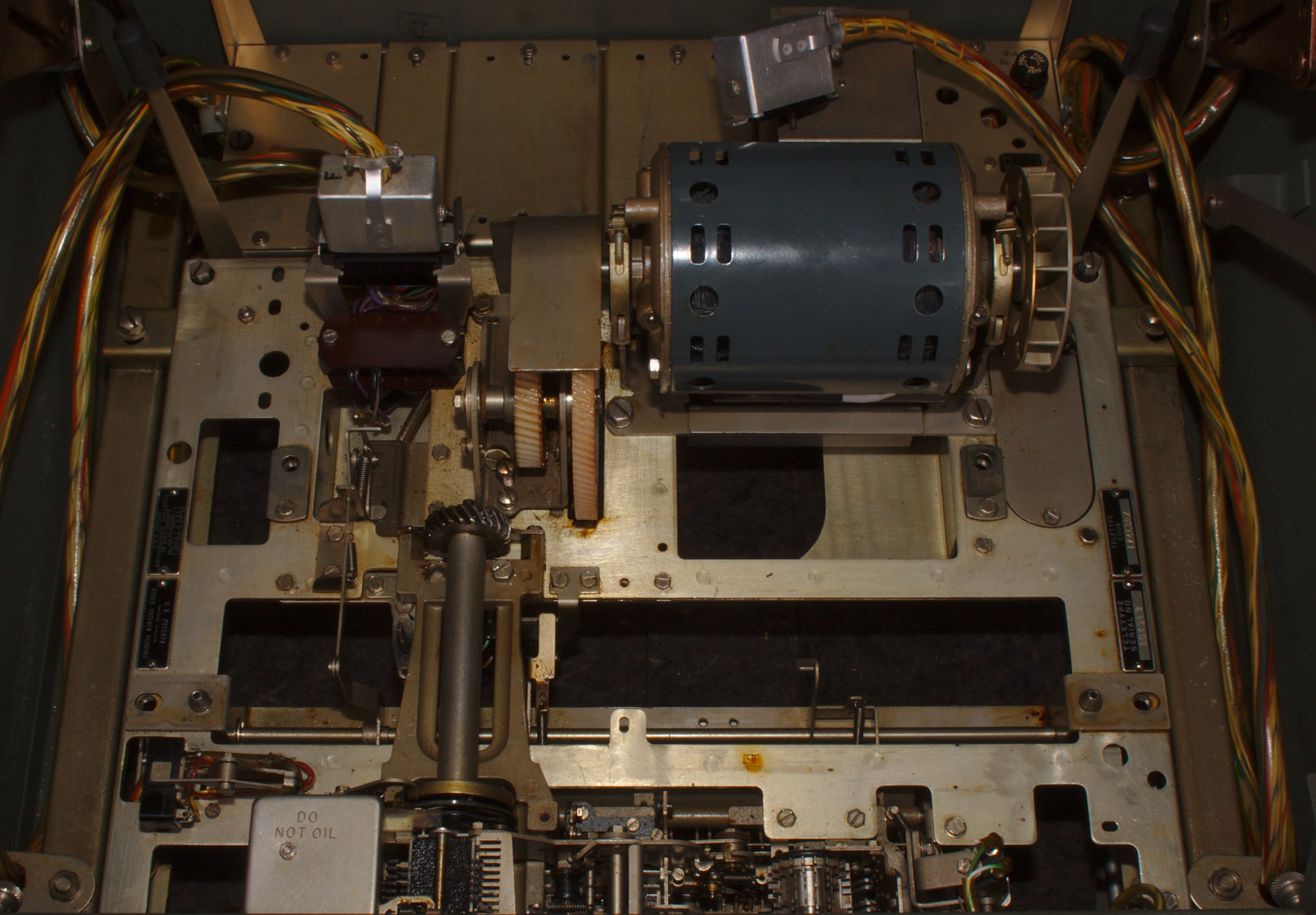
Typing Unit
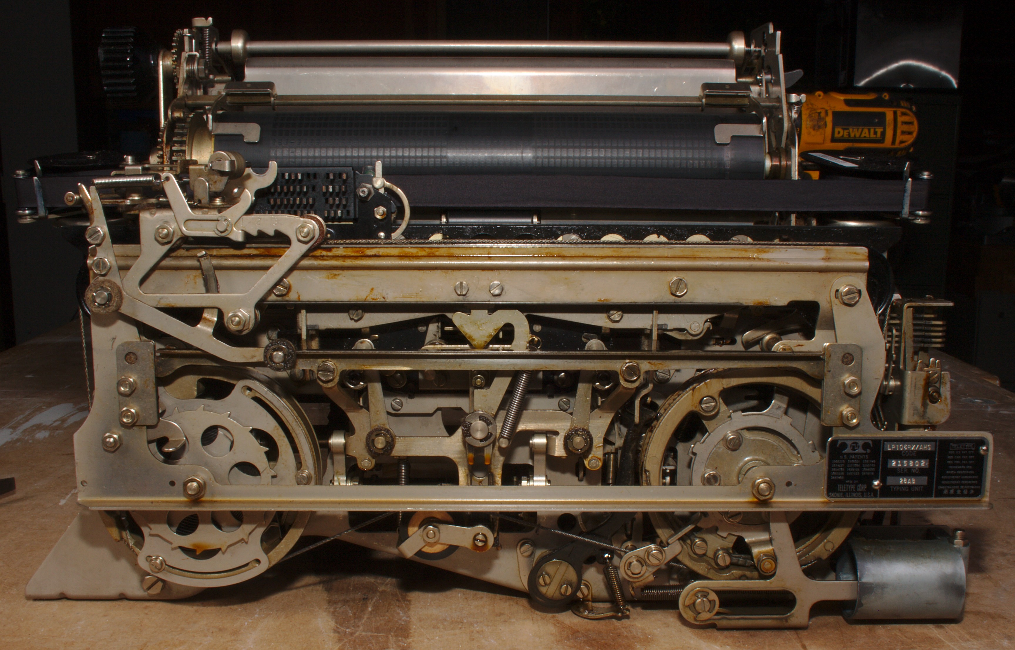
The Typing Unit. Note the two large carriage drive wheels on the front, and the dashpot (shock absorber) at the bottom right. The transverse code bars of the type box positioning mechanism are visible just above and behind the serial plate as five parallel bars. In this photo the carriage is in its home position. Pardon the cordless drill photobombing on the right.
The typing unit is by far the most mechanically interesting part of the Teletype, due to the sheer number of functions it contains and the complexity of decoding a 5-bit serial word into a type box position. It contains a main shaft with no fewer than six clutches controlling various functions as well as a secondary drive shaft at a right angle to the first that transfers power to the mechanism that moves the printing carriage. The bulk of the complexity in terms of parts count is divided between the decoding mechanism and the type box positioning mechanism, with the remainder of the TU being relatively simpler.
The structure of the typing unit is provided by two sheet metal frame pieces, one on each end of the unit, and a number of functional structures and support rods that spread between those frames. It is held to the keyboard unit by four screws, and removing these four screws allows it to be lifted out of the Teletype machine as an assembly for maintenance or repair. The keyboard is non-functional with the typing unit removed, as drive power for the keyboard is transferred through the drive shaft of the typing unit.

The bottom of the typing unit, showing its drive train. The incoming drive gear is the nylon gear about 1/3 in from the left, and the black helical gear just left of that transfers power to the keyboard unit at right angles. The six clutch housings are visible as the smooth metallic disks with a screw collar, although the clutch for the decoding mechanism is obscured by a plate and spring at the right-hand side.
The main shaft of the typing unit is readily visible from the bottom. Power is transferred into the unit from the motor output gears via a large nylon gear. The rotational speed of this shaft sets the timings for everything in the unit, so the gearing between the 3600 RPM motor and the nylon drive gear on the main shaft in the typing unit determines the rate of the unit. For 60 WPM (as used in Amateur service), the main shaft of the typing unit rotates at 368 RPM. The keyboard unit is driven from the main shaft of the typing unit at a right angle by a helical gear, such that the keyboard unit and typing unit operate at the same speed. Power for the carriage mechanism is also taken off the main shaft at a right angle via helical gears to the spacing shaft.
A series of six normally-open clutches ride on the main shaft, each one engaging for 1/3, 1/2, or one full rotation when tripped. One full rotation of the main shaft corresponds to a single character decode, so no single operation driven by this shaft requires more than one rotation to complete.
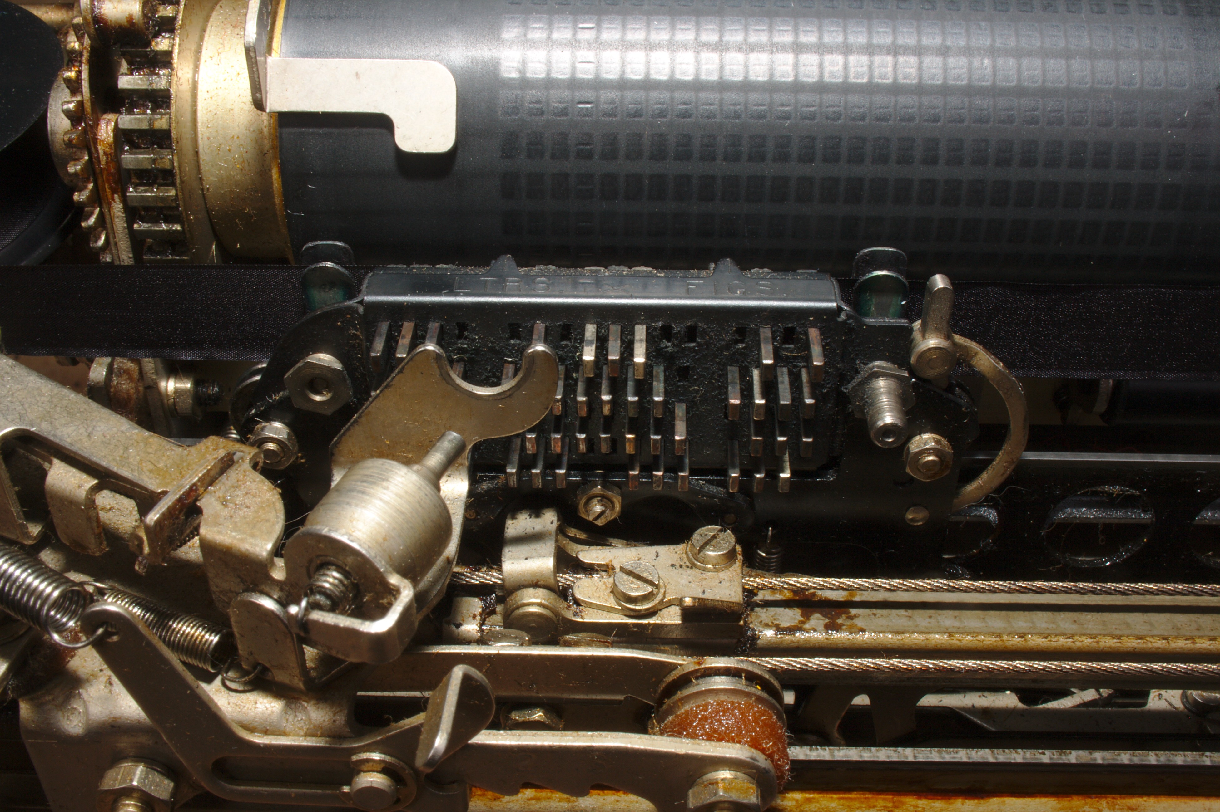
Incoming signals pass into a selector magnet assembly on the right-hand side of the typing unit (all references to position are from the operator’s seat point of view) just behind the carriage mechanism. The armature on that assembly depresses or does not depress a series of levers that are pushed one at a time by a series of rotating cams, depending on whether the signal line holds a mark or a space at that instant in time. The rotating cams are on a clutch on the main drive shaft that is released by the start bit and that rotates exactly once per incoming character, triggering each bit lever in turn. These levers set up a bank of bars that run the width of the typing unit and are used to locate the type box for the hammer strike at the end of the character.
(Detailed information on how the type box is positioned will appear here once I have had time to digest its mechanism.)
The type box and a hammer that strikes the selected character ride on a printing carriage driven by two large wheels at the bottom of the typing unit via braided steel cables. The right-hand wheel contains a ratchet face and advances one tooth for each printing character or space. The left-hand wheel contains a coil spring that is used to return the carriage to the left in the time it takes to decode the next received character — about 160 ms. This requires a substantial amount of force, and to avoid crashing the head into the home end of the unit on each carriage return, the right-hand wheel additionally loads an air dashpot over the course of the first few characters per line which is discharged at the end of the carriage return travel to cushion the halt of the carriage.
At the end of each character decode, the printing carriage is lifted up about one character height (so that its resting position is below the line being typed, to permit the operator to read text as it comes in), the type box is adjusted so that the decoded character falls under the hammer, and the hammer strikes the type box onto the platen through the ink ribbon and paper. The total travel for the type box with respect to the hammer is about one inch in both the vertical and horizontal directions for each character decode, as only one half of the type box is used at any given time. Decodes of the LTRS and FIGS characters cause the type box to shift to the right or left, respectively, putting the appropriate half of the type box under the hammer. Each half of the type box is labeled on its top face with stamped lettering, and a protruding finger with a stamped hairline indicates where the next character will strike on the platen.
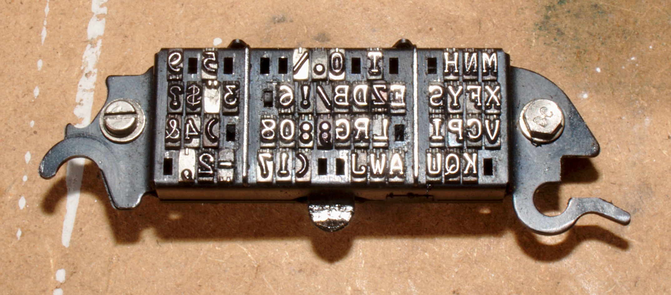
The type box from my Teletype. The right half (eight columns) of this image is LTRS, while the left is FIGS. Those spaces that contain no type transfer bar are non-printing characters. The hammer strikes on every character, and simply transfers nothing for characters that do not print.
The type box itself contains the 64 “characters” expressible in Baudot — 32 for the LTRS case and 32 for the FIGS case. Several of these characters are the same in both cases (CR, LF, LTRS, FIGS, BLANK, SPACE), and a number of them do not print a character on the page (and thus have no type transfer bar). The type box is easily removable from the printing carriage by releasing a sprung lever on the right-hand side and rotating it up and to the left using a screw that protrudes for that purpose. It can then be unclipped from a pin on the left side and removed. Reassembly is the reverse. There were a variety of character sets encoded in Baudot, sharing the same letter positions but with different fgiure sets, that could be exchanged in a given Teletype unit by replacing the type box. In addition, for a given encoding there were up to three (or occasionally more) fonts available. The font depicted in the banner at the top of this page, and present in my Teletype, was called Murray.
Keyboard Unit
The second most complicated unit in the Model 28 KSR is the keyboard. It contains the keyboard itself and the signal generator (which turns keypresses into serial Baudot signals), as well as providing a mount for the motor unit and terminal unit. On some teletypes it additionally includes an automatic answer-back mechanism capable of spooling out 20 Baudot characters.
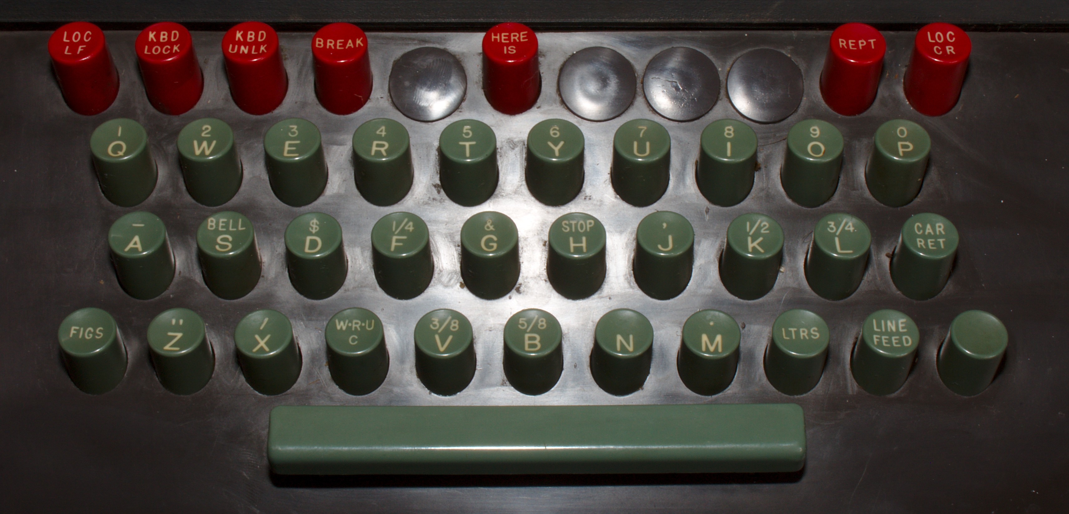
The keyboard unit chassis (top) and keyboard keys themselves(bottom). The motor unit is still mounted to the keyboard unit in this photo, and the automatic answer-back mechanism is visible at the bottom. Note that the keyboard keys do not match the character set in the type box!
The keyboard itself has three rows of green “regular” typing keys plus a spacebar and a top row of red function keys that activate functions within the Teletype. Due to the character set size limitation of Baudot, a fourth row of keys containing numbers (such as is found on a modern keyboard) is not necessary. Instead, the numbers 1-9 and 0 are found on the top, QWERTY, row of the keyboard in the usual keyboard order. Similarly, instead of a shift or caps lock key, there is a FIGS key to the left of Z and a LTRS key to the right of M that shift between the LTRS and FIGS cases. Another obvious difference from a modern keyboard is the separation of the return or enter key into separate carriage return (CR) and line feed (LF) keys.
The set of available red function keys on a given Teletype unit varies, although all Model 28 KSRs have the local linefeed, keyboard lock and unlock, and local carriage return keys. It may be the case that all units also have a repeat and break key, but I am not sure. The local CR and LF keys manually trigger the typing unit to issue a carriage return or line feed, respectively, without requiring the corresponding character to be decoded by the typing unit signal decoder. This allows a line of text that is over-running the right-hand margin to be brought back onto the page without (overly) disturbing the incoming data. The keyboard lock key latches a bar into the keyboard, preventing any other key from being depressed while it is down, while the keyboard unlock key releases the keyboard lock key and its associated mechanism. The repeat key causes a key pressed down in tandem with it to be repeated as long as the repeat key is held (rather than issuing only once, which is the usual behavior). The break key simply opens the loop connected to the keyboard signal generator, forcing it into the spacing condition as long as the break key is held.
On the pictured keyboard there is also a HERE IS key, which triggers the automatic answerback mechanism (partially visible in the keyboard unit photo at the bottom) to send the Baudot characters encoded on its code wheel. It contains nineteen Baudot-encoded sheet metal keys, each sensed by a lever that communicates its level to the signal generator. This key, and the corresponding mechanism, is not present on all Model 28 KSR Teletypes.
Each green key on the keyboard is connected to a key lever that passes under a series of code bars in the keyboard unit chassis (one for each bit of the Baudot code) similar to those in the typing unit. Depressing the key moves slots on the key lever such that the code bars in the keyboard can shift according to the mark/space code representing the key that has been pressed. The code bars are then read out by a series of cams (again, similar to the typing unit but in reverse) serializing this bit sequence onto the wire.
Maintenance
I have already crossed several maintenance bridges and had to learn some things about the teletype to get it to 100% operating condition. Some of those things I have learned are gathered here.
Motor Unit

Figure 1. Note the shattered insulation on this wire. The others were not better, and worse in places. Slight flexion of the wire caused additional shattering.
After receiving my Model 28, I was able to operate it several times without issues. However, after doing some cleaning, it started tripping the GFCI outlets in my shop. I first assumed that oil on one of the connectors had accumulated enough crud to create a leakage path, and thoroughly cleaned all of the connectors I could reach; however, this did not fix the problem. By disconnecting mains-powered components and units one at a time (there are relatively few, and many of them are reachable either on the terminal strip in the top of the cabinet or their own terminal strips) I was able to isolate the leakage to the motor unit. Upon removing it from the keyboard unit, I found that the insulation on the three lead-in wires on the motor itself had become extremely brittle with age (and possible oil saturation) and the insulation had shattered. (See Figure 1.) This shattered insulation allowed contact with the motor unit chassis, which leaked to the cabinet and thereby to the third prong on the line cord.
There are a couple of pieces of good news here: one, the massively forward-thinking engineers at Western Electric actually designed the Model 28 (or at least modified it surprisingly early, I’m not sure which) with a three-prong line cord, and bonded the third prong to the cabinet as well as the chassis of the keyboard unit (which in turn grounds the chassis of the typing unit and motor unit). Therefore, this leakage could not set up a dangerous voltage on the cabinet. Two, the GFCI did its duty and tripped when the leakage was detected, protecting the circuit and eliminating the possibility of a less-than-perfect short leaving a still-dangerous voltage on the cabinet.
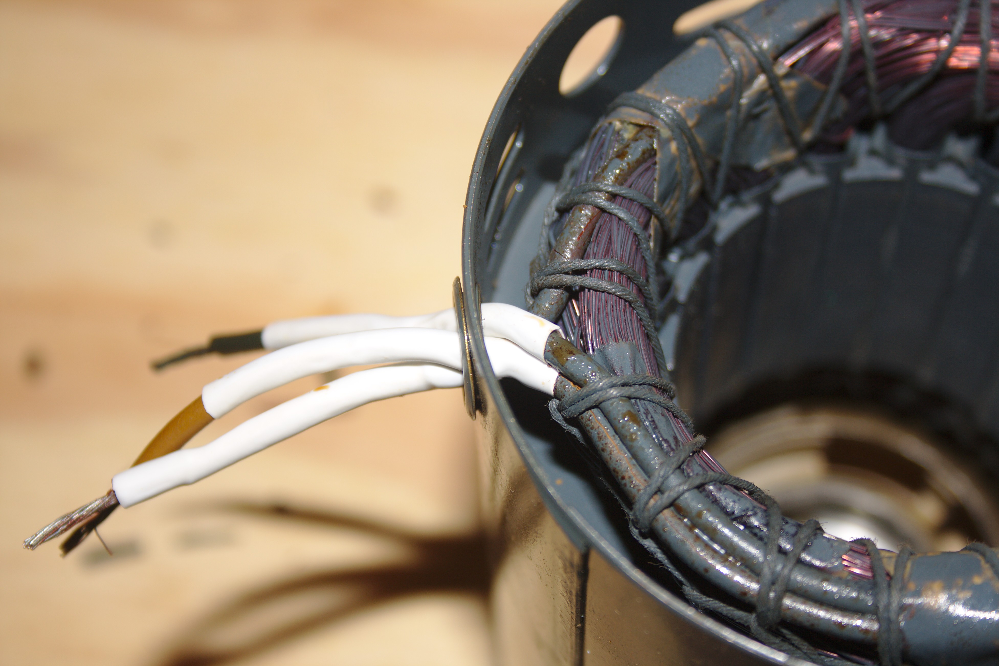
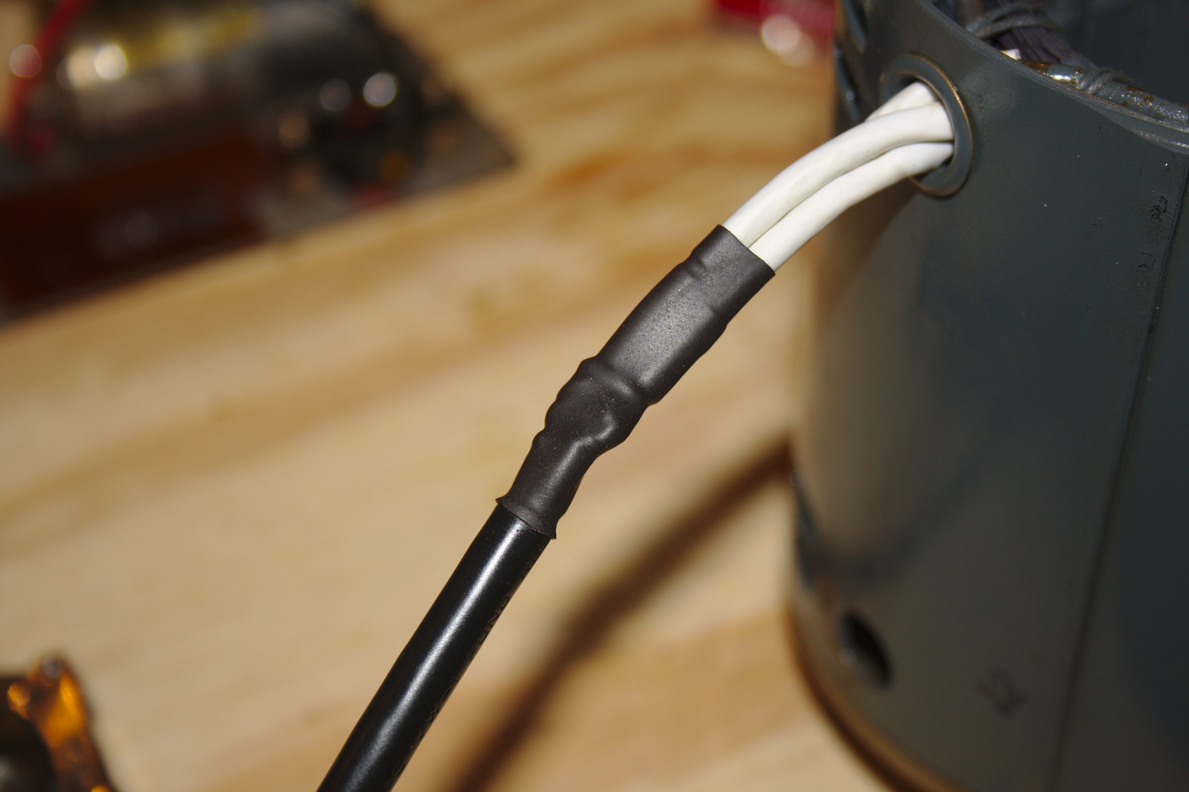
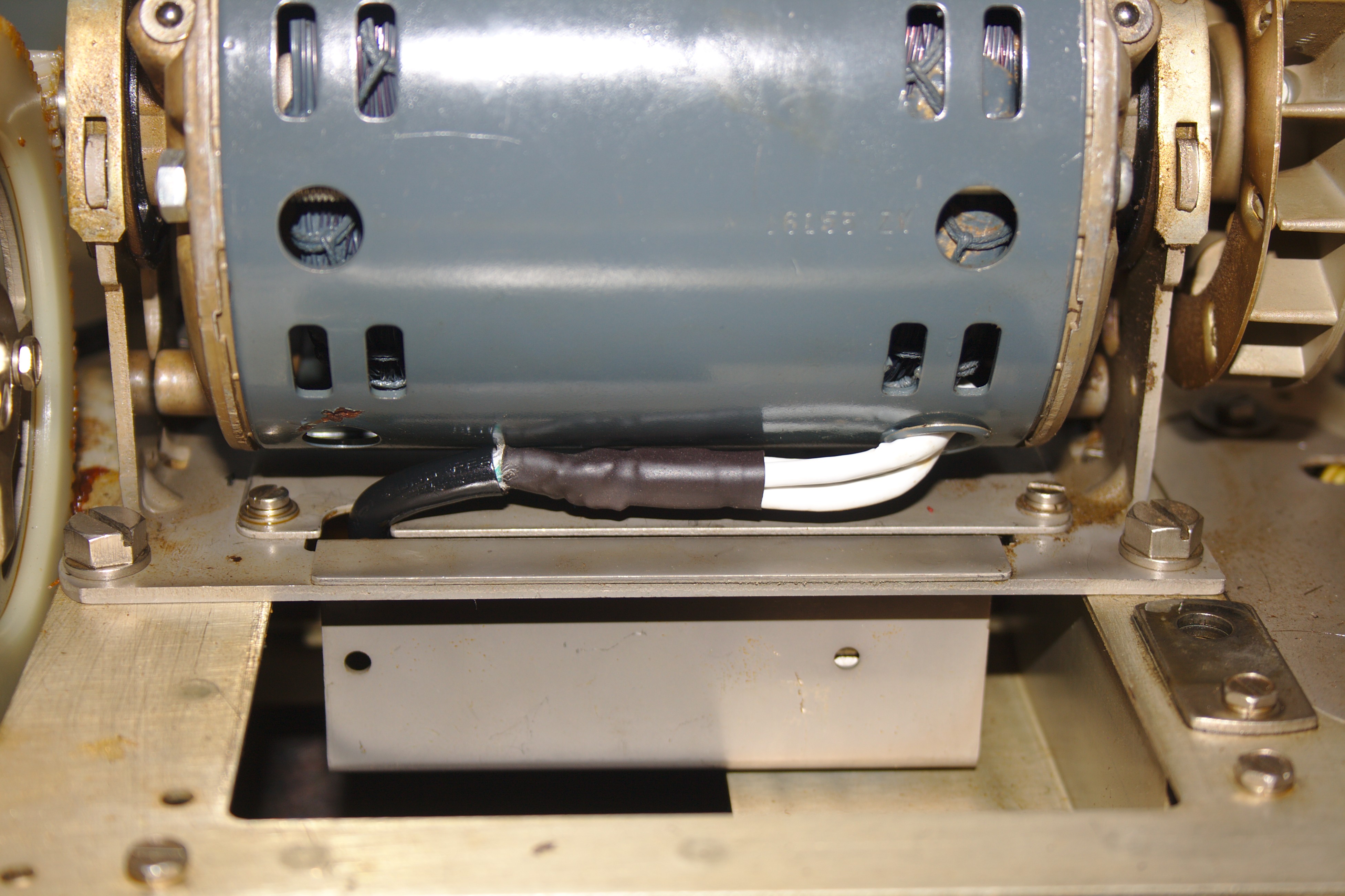
Figure 2. The fixed motor leads. First, the motor leads are shrink wrapped back into the case where they are protected. Second, an IEC cable is shrink wrapped to the protected leads. Third, the motor is remounted on the motor unit chassis and the chassis replaced in the keyboard unit.
The bad news is that the lead-in wires on the motor are tied (and possibly epoxied) into the windings. However, once they enter the motor case, they are rather firmly bound in place with lacing and cannot move much, so the insulation past the grommet at the case was in pretty good shape. I was able to carefully cut and strip the lead-in wires near the motor case, solder on a short length of line cord (cut out of an IEC power cable), and wire it to the appropriate terminals on the motor unit chassis. There are three wires leading into the motor, two for the primary winding and one for the outboard end of the starter winding, so a three-wire line cord does the job neatly. I do not know how long the line cord will survive in that environment (I suspect the original wires failed due to the large quantities of oil in the motor unit and the teletype cabinet in general), but so far it is at least not leaking to the chassis!
Having not examined a large number of Teletype motor units, I don’t know if this insulation failure is endemic or anomalous. However, I would consider it prudent to examine the motor lead-in wires on any Teletype in my possession. Note that the two-wire zip-cord style wiring connecting the motor unit to the motor terminals on the keyboard unit was in excellent condition and did not require remediation.
Lamps
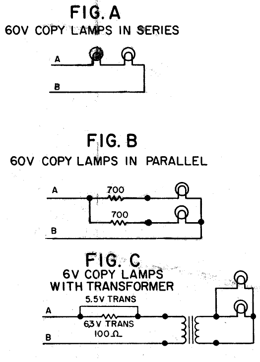
Figure 3. The three lamp circuits, from document WO470 sheet 1 on Navy Radio’s Teletype wiring diagram list. All circuits are powered directly from switched mains voltage. The complete schematic is here.
There are three lamps in most Model 28 KSR console cabinets. Very early cabinets contained one fluorescent lamp to light the copy as it prints and one incandescent lamp to light the margin indicator when the printing carriage nears the right margin, but later cabinets use two incandescent lamps to light the copy and eliminate the fluorescent bulb and its associated ballast and starter.
Unfortunately, the copy lamp circuit has changed several times over the years (aside from the fluorescent-to-incandescent changes, which is at least not terribly difficult to identify due to the lack of ballast and starter). Therefore, identifying the lamps that go in a given unit takes a little bit of sleuthing. Figure 3 shows the three incandescent circuits. The cabinet on my Teletype uses the copy lamp schematic in Figure 1C, which requires two 6.3 V #82 lamps. I could not find those locally, but I was able to find two 1004 (a 12 V lamp with the same BA15d base and a similar envelope) lamps at a local auto parts store and I installed them temporarily. It turns out that they provide a very pleasing level of light output (at lower current than the #82 lamps due to running under voltage) and I would recommend them.
The margin indicator lamp situation is at least simpler, if a bit of a disappointing design. Due, I assume, to the original incandescent copy lamp circuit (Figure 1A) of two 60 V lamps in series driven off the mains voltage coming into the cabinet, it is a 60 V lamp. Since it is run off the mains voltage with no other lamp in series, it requires a dropping resistor to bring its filament down to 60 V. That dropping resistor, per the schematic, is 600 Ω. Assuming an equal drop across the resistor and lamp with a 120 V line, that’s 6 W dissipated just to bring the voltage down! This lamp was also not readily available to me (and in fact I do not have an identifier or model number for it), but I was able to find a GE appliance bulb with a T7 envelope (I assume the original was G6, like the #82, which is much smaller, but the T7 fits), BA15d base, and 15 W dissipation at 120 V. Rough calculations (I don’t know the exact resistance curve of the element by voltage) suggested this would be in the ballpark of the right drop to work with the (measured 700 Ω) dropping resistor, so I tried it. Bingo! With a line voltage of about 124 V, it dropped 61.8 V across the lamp! I would recommend this replacement as well.
Note that for full-page justfied copy, the margin lamp is only on a bit less than 10% of the time, so the 12 W dissipated in that circuit is less hateful than it seems — but still, by modern standards, that’s a heck of an indicator budget.
Lubrication
There seems to be some rough agreement in the lubrication front, but I’ve seen quite a few opinions. There’s a lot of discussion on this off and on on the Greenkeys mailing list (see Resources, below). I haven’t had my Teletype long enough to be completely sure the lubricants I chose will not cause damage or prove problematic in the long run, but I selected 20 weight full synthetic motor oil and Lucas Oil Red-N-Tacky for lubricating my Teletype. So far they seem to be working fine. Non-detergent oil is recommended as the detergents break down with time, although I have used detergent oil as it is what I had available. Time will tell. There are extensive manuals from Teletype that give the points to be lubricated and quantity of lubricant used. The total quantity is “not much” — I saturated every felt in my unit, greased all of the gears and several bearings, and used a total of maybe 3-4 cc of oil and 1 cc of grease.
Resources
Most of the information I have has come from elsewhere. I was fortunate to buy my Teletype from Bill Strangfeld, W8FIX, a fellow ham who has been very helpful in getting it operating at my station and in helping me find resources for understanding it. Here are some of the resources he has provided me with, as well as some that I’ve found on my own:
- navy-radio.com: This site has a ton of information on Teletypes and related equipment, including military and Teletype manuals, wiring diagrams, installation guides, etc. There are literally thousands of pages of documentation for the Model 28 alone.
- The Internet Archive: archive.org has lots of good information in general, but in particular it has back issues of 73 magazine and the RTTY content therein.
- The New RTTY Handbook by Byron H. Kretzman, W2JTP: Bill tipped me off to this book, and it has some great period information about Teletype equipment and setups, as well as a variety of circuits for building homebrew RTTY terminals, autostart mechanisms, and other interesting material. I was able to get a copy for only a few dollars including shipping.
- The Greenkeys mailing list: This is a list of Teletype users and collectors with moderate volume (a few dozen to a hundred or so messages a month?). There’s some really great stuff, but being a mailman pipermail archive it does take some digging to get to it.