If you enjoy working on vintage equipment, or just enjoy vintage equipment, or just like a nice analog needle, a vacuum tube volt meter (VTVM) is a handy thing to have around. Being vintage equipment itself, it satisfies the vintage equipment buff, and who doesn't like an analog needle? When you add in the fact that it's actually useful for working on older equipment, sometimes more useful than a modern digital multimeter (DMM) or volt-ohm meter (VOM), it's a wonder everyone doesn't have one!
The Practical Role of a VTVM
That last claim may require a little bit of explanation — why would fifty year old technology be superior to state of the art modern equipment? It does require some qualification, but the basic reason is that requirements have changed over the years. Tube-type equipment was full of high impedances and high voltages. Solid state equipment tends to have lower impedances and lower voltages. The impedance of the circuit you're working on has important implications for the test equipment you use on it; if the test equipment input is not of substantially higher impedance than the circuit under test, measurement effects will disturb your readings to a potentially unacceptable degree. They can even cause the circuit to stop functioning properly! The voltages in use dictate the voltages that the measurement equipment must be able to withstand.
The modern VOM is often 20 kΩ per volt DC input impedance, and even lower for AC input impedance. This is within an order of magnitude of many high-impedance tube type circuits (for example, the signal driving a grid, which may have a single-digit-volts negative DC bias), and very likely to load the circuit under test. DMMs often have much higher input impedances than the typical VOM, and are more appropriate in that respect for working on high impedance vintage circuits.
Both modern VOMs and modern DMMs are likely to have a maximum input voltage range of about 400-600 V. Vintage equipment, particularly transmitters and CRTs, commonly have supply voltages of 650 V to several thousand — or even 10 kV or more — volts. This necessitates the use of special high-voltage probes or voltage dividing inputs.
By contrast, the typical VTVM has an 11 megohm input impedance for DC measurements, with 1 meg of that in the probe tip itself — limiting capacitive loading on the circuit under test. VTVMs are typically capable of measuring 1.5 kV or more DC without special probes, and sometimes several times that for AC voltages. These properties make it ideally suited for working on equipment of its own era. Let's be realistic: it is certainly possible to buy a DMM that meets these requirements. However, it's going to be more expensive than a working used VTVM, and you'll have a very hard time convincing a vintage equipment buff that the DMM is worth those confangled transistors!
The RCA Senior Volt-Ohmyst WV-98C
The WV-98C is an example of a late VTVM (mid 60s vintage) of very typical circuit design and exceptional build quality. It is housed in a heavy die cast aluminum case (the assembled meter weighs about 6lbs) and sports a large, easy-to-read meter face of about 8" across the diagonal. Some models have a mirrored ribbon across the meter scale for eliminating parallax error in reading the needle. Like most VTVMs, it runs its tubes (of which it has two — a 6AL5 dual diode and a 12AU7A dual triode) on AC line voltage, and uses a dry cell battery for a voltage reference when measuring resistances.
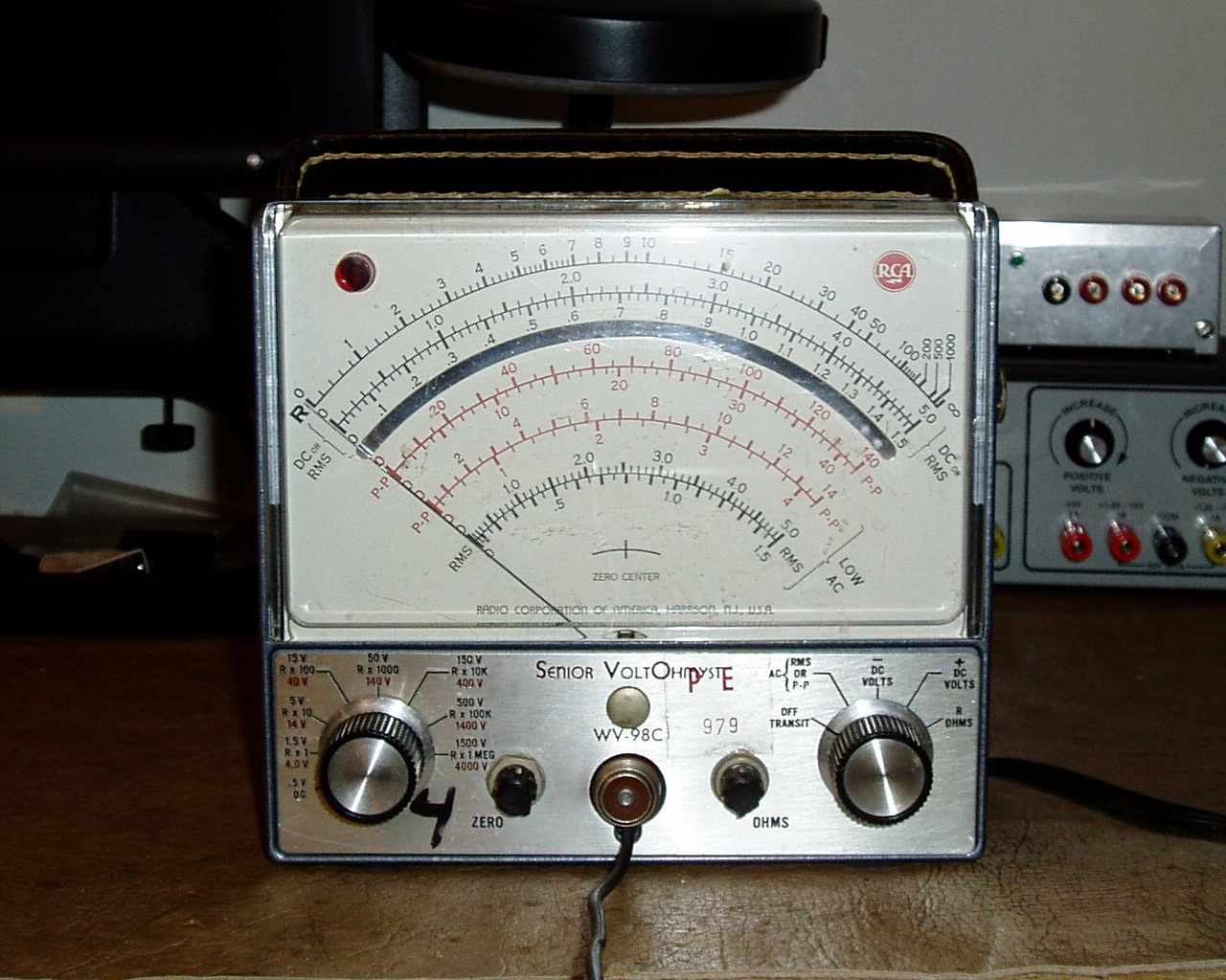
Figure 1. The face of the Senior Volt-Ohmyst WV-98C. Note the large meter movement and mirrored background.
I acquired a WV-98C (shown in Fig. 1) at the La Porte County Amateur Radio Club's "Cabin Fever" Hamfest in February 2013. It was purchased in unworking condition, but the meter movement was free and the needle bounced a bit when working the controls — suggesting it would be quite possible to bring it back to life. As the external condition suggested that the meter had been cared for during its life, I paid $20 and took it home with me.
Very Simple Repairs
Upon opening the case, the absolute cause for no response on the ohmmeter function and likely cause for no response on the other functions were obvious. The reference battery was missing, and the previous denizen of its holder had ruptured and corroded nearby components before being removed. This is a very common problem in VTVMs, as dry cell batteries do not last forever.

Figure 2. The bad (or presumed bad) components from this particular meter.
I disassembled the top chassis bracket (which had caught the majority of the leaking battery acid) by removing the primary wires of the power transformer and a handful of screws, then scrubbed it down with a wire brush and warm water. It did not appear that there had been major damage to any components outside of the top bracket, and the transformer (housed in that bracket) looked fine, so I went ahead and powered the meter back up and started poking around. Some quick probing revealed that while there was 120 VAC on the selenium rectifier, no current was passing through it and there was 0 VDC and only a very small phantom AC voltage across the power supply filter capacitor. I was not overly familiar with selenium rectifier failure modes, but some quick web searches and consultation of vintage equipment lists revealed that it is very common for selenium rectifiers, and particularly abused selenium rectifiers, to fail open. That appeared to be the situation in this case, and it resulted in no B+ or bias voltages in the meter.
Selecting a silicon diode rectifier: The original text of this article (below) indicates that I installed a 1n4004, which is true. However, that diode failed in service after some time. When I put it in, I calculated that the 400 V reverse breakdown voltage of the 1n4004 was sufficient for this circuit, which is about 130 V RMS according to my true RMS multimeter. This ought to yield a peak voltage of about 370 V. However, there must be higher transients (or perhaps a surge hit the line at some point) because the 1n4004 failed in such a way that it developed about a 10 V forward drop and leaked backward when placed under high voltage. This took some time to identify, because it continued to work fine at low voltages such as those produced by a diode tester!
I don't know why I selected a 1n4004 in the first place, given that it was expected to ride within 10% of its maximum reverse voltage in normal operation, and that I have literally hundreds of 1n4007s on hand. Maybe it was just convenient at the time for some reason. In any event, I now consider the 1n4004 inadequate for this purpose, and would recommend a 1n4007 (which has a 1 kV reverse breakdown) instead.
Armed with a 1n4004 and a suitable high voltage electrolytic capacitor, I proceeded to replace both the selenium rectifier and the filter cap that followed it (on principle — the existing cap was cosmetically in OK condition, but old electrolytics often don't work well, and sometimes fail catastrophically) to bring the 88 V B+ line and -40 V bias voltage back into spec. The failed rectifier and offending capacitor can be seen in Fig. 2.. Some corrosion is visible on the rectifier stack. Before testing the voltages and determining that it was in fact bad, I cleaned it up. Prior to cleaning it had a large amount of corrosion caked on its outside surfaces, including growths of some sort of crystalline structure on its cathode.
The battery holder contacts and its hookup wires were also quite corroded, and the hookup wires were not soldered to the battery holder. I suspect the holder was a replacement, and the corrosion was simply due to the old battery acid not having been cleaned out of the cabinet before closing it back up. I replaced the hookup wires for the holder, as well, and installed a new alkaline battery.
Powering the meter back up after replacement revealed that there were no other substantial problems. All resistance scales read within a couple of percent on the ohmmeter function, and the AC and DC scales read correctly up to about the 50/150 V scales (I didn't have convenient sources for the higher ranges).
Note on Selenium Rectifiers: While selenium rectifiers are rectifiers in the same fashion as a silicon diode, they aren't always interchangeable! Selenium rectifiers have a relatively high forward resistance (on the order of tens of ohms or more) and can have a relatively large forward voltage drop. Some designs depend on this resistance or voltage drop for correctness or even safety. Ensure that these characteristics are not important before replacing a selenium rectifier in vintage equipment! A series resistor of appropriate value can be used to compensate for the relative superiority of the silicon diode if necessary. In the case of the WV-98C, the B+ voltage is not particularly high and the current drain is minimal, so these factors don't come into play.
The Finished Product
Fig. 3 shows the replacement components in place in the meter. The replacement filter capacitor is the black axial capacitor near the center of the frame, and the rectifier diode is just visible behind the black lamp wire pair to the right of the capacitor.
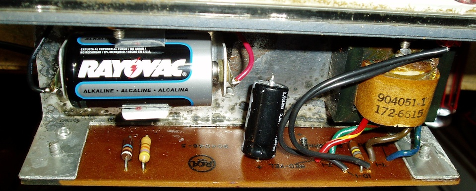
Figure 3. The replacement components installed in the meter. Both the new capacitor and the rectifier diode are visible toward the center.
For an hour or so of work and $0.50 in components (the filter capacitor is a ridiculously oversized 650 V unit, which drove up the cost!), this meter is back in service! That's what I call a good evening's pastime. The case and frame could use a bit more cleaning, but the danger of continued damage from moisture and/or battery chemicals is past. Sometimes the simple jobs are extremely satisfying!
