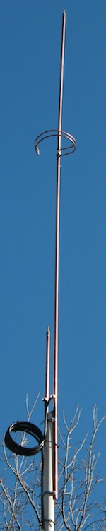
Figure 1. The finished J-Pole mounted on a PVC mast. Note the common mode choke formed from a coil of the transmission line performing balun duty.
This page documents a build of a 2-element 1/2 wave collinear J-Pole performed by Harry, KC9EOT, and myself, KB8OJH. We fabricated two identical J-Poles using the dimensions in this document, and both of them performed quite well, with a resonant frequency toward the lower end of the 2-meter Amateur band and a VSWR of 1.5:1 or better over the entire band.
We have not yet performed field strength tests on the resulting antennas, and they have not been in service long enough to give detailed performance results. However, preliminary testing suggests positive Tx gain relative to a loaded 5/8 wave antenna (as expected). More details will be provided as we learn more about their performance.
There is nothing particularly novel or clever about this build, we simply felt that it turned out very well. Additionally, we took the time to document dimensions carefully, and those dimensions are included here.
For general information on constructing a copper pipe J-Pole, see
The ARRL Handbook.
The ARRL Antenna Book
additionally contains plans for a mobile 1/2 wave collinear J-Pole
constructed from a CB whip and stainless hardware, featuring a
phasing section similar in design to that which we used.
Materials
For this build, you will need the following materials. We used materials somewhat dissimilar from any collinear J-Pole build we are aware of, but none of them are surprising, and all of them can be found at your local hardware store. Most of them are in the plumbing aisle!
- (~140") of 1/2" Copper Pipe
- (41 5/8") 1/4" Soft Copper Tubing
- (12" 5/8") diameter Wooden Dowel
- (1 1/8") 1/2" PVC Pipe
- (1) 1/2"x1/2"x1/2" Copper Tee
- (1) 1/2" Copper 90 degree Elbow
- (2) 1/2" Copper End Caps
- (2) 1/2" Copper Pipe Hangers
- (4) 6-32 1" Brass Screws
- (4) 6-32 Brass Nuts
- (2) 1/4-20 3" Brass Screws
- (4) 1/4-20 Brass Nuts
- Pipe Flux
- Solder
Very judicious use of the 1/2" copper pipe may allow for the entire unit to be constructed out of a single 10' pipe section. We used one 10' section plus about 18" for each antenna in our build. The entire BOM for this antenna comes up at about $30-35, depending on specific hardware selection. You will also need some tools:
- Blowtorch
- Pipe Cleaner or Steel Wool
- Pipe Cutter
- Drill Press
- 17/64" (or 9/32, not critical) Drill Bit
- 9/64" Drill Bit
- 1/4" Drill Bit
- Pliers
- Screwdriver to fit each of the above screws
- Adjustable Wrench
A drill press probably isn't absolutely necessary, but it certainly makes drilling on the various convex surfaces much easier. We also found a small, butane-powered blowtorch (visible in Fig. 4, below) handy for some of the smaller soldering jobs.
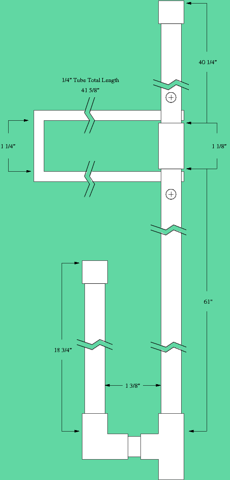
Figure 2. Dimensional diagram.
Dimensions
The dimension diagram on the right gives the overall layout of the J-Pole. A traditional J-Pole consists of a 1/2 wave radiator and a roughly 1/2 wave tuning "U" at the bottom of that radiator. The collinear J-Pole adds a 1/2 wave phasing section to the top end of that radiator, with another 1/2 wave radiator above that. This causes the two collinear 1/2 wave radiators to be fed in-phase, causing their signals to reinforce.
The bottom J-Pole is roughly a standard J-Pole. We found that the dimensions which tuned up properly in this collinear configuration were somewhat longer than the standard J-Pole dimensions found in the ARRL Handbook, ARRL Antenna Book, and around the web. Conductor diameter, composition, and other factors affect the length of antenna elements, so possibly our slight departures from published designs contributed to this. In addition, note that we appended adjustments to the tuning section and upper radiator, so the pipe lengths are somewhat short of the finished dimensions.
The short tuning section of the bottom J-Pole is 18 3/4" of pipe, fitted into an elbow joint below and an adjustable cap (see the next section) above. It is attached to the radiating element by way of a 1 1/8" nipple into the T fitting.
The lower radiating element and remainder of the tuning section is a 61" piece of pipe fitted into the top of the T fitting. This is the only element of the antenna which is not adjustable for length; fortunately, it does not appear to be extremely finicky, and trimming the tuning section affects its resonance.
The upper radiating element is 40 1/4" long, and fitted with an adjustable cap in the same manner as the tuning section.
The upper and lower radiating elements are separated by the 1 1/8" piece of 1/2" PVC pipe.
The phasing section is constructed from a 41 5/8" piece of 1/4" tubing, bent into a "U" shape with the two long sides separated by 1 1/4" inches. Note that this is somewhat longer than 1/4 wave at 2 meters; this is offset by the fact that the phasing stub is inserted through the 1/2" copper pipe at both ends, reducing the length of the phasing section by well over an inch total.
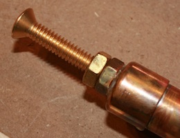
Figure 3. This adjustable end cap is constructed from a standard 1/2" pipe cap, two 1/4-20 brass nuts and a 1/4-20 brass screw. With a 3" screw in place, it provides more than enough adjustment for any eventuality!
Adjustable caps
The adjustable caps are constructed out of a standard 1/2" copper end cap and a 1/4-20 brass hex nut. Drill a 17/64 hole through the center of the cap end. Clean the end of the cap and one face of nut. Flux the two clean surfaces and place them together. Line the hole in the nut up with the hole in the cap, and sweat the nut in place. You probably want to do this after the cap is already sweated to its pipe section, or the nut is likely to fall off when you affix the cap! Once these pieces are soldered together, a 1/4-20 brass screw can be run into the nut to provide several inches of adjustment.
Construction
The lower J-Pole is simply sweated together. Likewise, the adjustment cap is sweated to the upper radiator.
To connect the two sections together, turn, file, or sand the 5/8" dowel section down until it can just be driven into the upper end of the 1/2" copper pipe making up the lower radiator. Drive a bit less than half of it into this radiator, then slip the 1 1/8" PVC section over top. The PVC should butt against the lower pipe section. Next, drive the top radiator down over the top of the dowel until the whole unit is sandwiched tightly together. Drill a 9/64" hole through both the 1/2" copper pipe and dowel several inches above and below the PVC spacer. Push one of the 6-32 screws through each hole, and tighten a nut down against the other side. Between the friction of the interference-fit dowel and the screws, the construction should be quite sturdy.
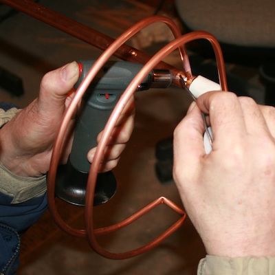
Figure 4. Harry (KC9EOT) soldering the phasing section in place. Note how it has been curled around the center conductor, increasing mechanical stability and reducing its footprint.
Figure 5. Top view of phasing section.
Having bent the phasing section into a U shape (as described above) 1 1/4" wide and roughly 20" long, curl it into a semicircle with a partial closure, as shown in Fig. 4 and Fig. 5, with the two legs of the "U" forming the curve. The 1 1/4" end section should be at the end of the outer semicircle, with the two open ends at the center. This forms a phasing section which is electrically equivalent to the dimensional diagram, but which will curve around the center element in a more compact and physically stable configuration. The radius of the curve is not critical; we used a 10" form.
The phasing section will pass through the 1/2" copper pipe both above and below the PVC spacer. 1/4" copper tubing is 1/4" actual OD, so drill two parallel 1/4" holes above and below the PVC spacer. These holes should be roughly 1 1/4" apart. Insert the two open ends of the phasing section through these holes so that the end of the tubing protrudes about 1/8" through the 1/2" copper pipe. Solder both sides of this pass-through, being careful not to ignite the PVC or wooden dowel.
The feedline connection points are formed by bending a copper pipe hanger's flanges over so that the hanger forms a "U" shape, with the mounting holes facing each other. Clip one hanger over each side of the tuning section, pass a 6-32 screw through the holes, and secure with a nut. You will need to move these points up and down to tune the antenna, but start somewhere between 1 1/2" and 2" above the bottom cross piece. It does not matter which element is connected to the center conductor of the coax, and which to the shield.
Tuning
We recommend tuning the lower section (the standard J-Pole) by itself, then assembling the complete antenna and tuning the upper section and performing fine-tuning. Remember that the antenna will couple with nearby conductive objects (including you!) as well as the ground, so make sure it is above the ground and away from interfering objects. We mounted the antenna on an 8' pole in a clear yard and checked tuning from about 18' away.
If you have an antenna analyzer, adjust the lower section for resonance near the center of the band, and a resistive impedance of as close to 50 ohms as you can achieve by moving the feed points up and down. We were unable to achieve quite 50 ohms on our build without throwing off the resonance. If you don't have an antenna analyzer, trim the antenna to achieve the lowest possible SWR toward the center of the band by alternately trimming the length of the tuning stub and adjusting the position of the feed points. If you have a particular frequency of interest which is not toward the center of the band, feel free to adjust accordingly!
Mounting
Like any J-Pole, this antenna is more or less electrically unconcerned about what may go on underneath the crossbar of the lower tuning section. By using a T fitting for the bottom of the lower radiating element, an additional piece of 1/2" pipe can be soldered to the bottom of the antenna, providing a convenient mounting point. The impedance at the bottom of the tuning section approaches infinity, so this mounting pipe can be grounded (such as to a grounded tower leg) if this makes mounting more convenient. Just be sure to keep metal objects, grounded or otherwise, out of other near-field areas of the antenna. Failure to do so will not only make tuning a frustrating experience, but it will potentially distort the radiation pattern.
Keep in mind when planning your mount that the completed antenna (without mounting stub) will be approximately 9 feet in length! It is not particularly heavy, and should not present an unreasonable wind load, but raising it by rotating through horizontal can put considerable stress on the mount.
Like any balanced antenna design, a choke or balun will be required at the feed point. The literature abounds with designs for VHF chokes and baluns. We chose to use a common mode choke formed by coiling the transmission line as close to the feed point as practical for the pictured installation.
Other Designs
Since building this antenna and writing this page, the Copper Cactus Dual-Band Super J-Pole Antenna by N7QVC was brought to my attention. His design is almost identical to the design we landed on (and predates ours). It must be a good one! note that his dimensions are much closer to the dimensions normally cited than ours.
