I recently purchased a 2-B in fair-to-middling cosmetic condition and unknown working condition ("receives signals on all bands") off the Internet for a moderate price. When I received it, it was as advertised — it did indeed receive signals on all bands. I haven't yet put it on a signal generator to see how sensitive it is in absolute terms, but it seems more or less OK. It generally functioned correctly in all respects, but it had two problems: the .4 kc pass band was misaligned somehow, and the muting circuit didn't work.
The rest of this page is about diagnosing and fixing the muting circuit. I haven't gotten to the .4 kc pass band yet. I wanted to pair the receiver with a Central Electronics 20-A transmitter (probably a CE 200V instead, now, as I acquired one at Dayton), and that was going to require muting, so I lit in on trying to find the problem and a solution.
Update 4/11/2014: Garey Barrell, K4OAH, provided some great feedback and corrections for this page, which I have incorporated below. His contributions are marked with [Update 4/14], and consist of:
- Correction of the term “grid leakage” to “grid emission” and correction of the description of the phenomenon;
- The reason for the AVC terminal on the back panel; and
- C69 construction.
The Symptoms
As I received it, the symptoms of the muting circuit in the 2-B were as follows:
- When the rig turned on, everything worked. Flipping the STBY/RCV switch to STBY kicked the S meter to the S9+60+ pin, flipping it to RCV received normally.
- Leaving the rig in STBY, as it warmed up, after 4-5 minutes the S-meter started drifting downward. As it passed down past S-9 or S-8 or so, background static started to become audible. Strong signals probably leaked through, too, but I never checked. It would eventually drift down to S-1 or S-2.
- Even after STBY had ceased to function, the RF Gain knob worked normally. Turning it fully counterclockwise would mute the receiver.
Initial Diagnostics
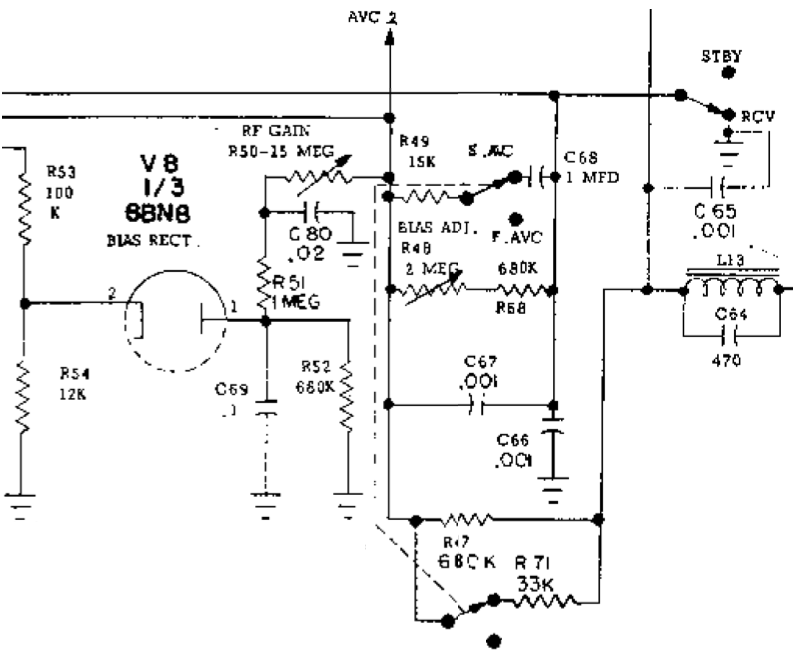
Figure 1. Excerpt from the 2-B schematic showing the bias supply. AC from the main power transformer enters at R53 at the top left.
I mention the S-meter above not merely because it's a visible symptom, but because, as in many radios of this era, the S-meter deflection is driven (indirectly, in this case) by the AVC voltage. The muting circuit operates by driving the AVC voltage on the grids on the IF tubes so low that the tubes are completely shut off. The sagging S-meter therefore told me that the AVC voltage was probably falling for some reason. The slow sag as the rig warmed up made it seem likely that a component was either warming up itself (either intentionally or due to an unintentional current load), or being indirectly warmed by a nearby warm component.
The 2-B conveniently brings an AVC voltage terminal out to the back panel; [Update 4/14] this is so that the operator can add an additional capacitor to the slow AVC time constant if desired. I put a high impedance DMM on the AVC terminal, flipped the rig to STBY, and powered it up cold. After a few seconds for the 6X4 rectifier to warm up, the AVC voltage rose to about -6.5 V, but immediately started drifting "downward" to about -1 V as the rig warmed up.
The first logical place to look on the schematic was the bias supply. Figure 1 shows an excerpt of the 2-B schematic depicting the bias supply. A tap off the main transformer is rectified by a diode section of V8, a 6BN8, then filtered by some surprisingly tiny caps — surprising, that is, until you notice that the first thing the supply passes through is a 1 MΩ resistor and the values just go up from there.
Looking over this schematic and applying my own rudimentary electronics troubleshooting skills (as well as some Internet research), I decided that the list of most likely and easiest to check culprits in the bias supply (not necessarily in likelihood order) were:
- V8, the supply rectifier, an 8BN8
- V6 (not shown), the AVC amplifier, a 6BF6
- R48, the "RF SENS" pot on the back of the rig
- C68, a 1 μF paper capacitor
- C69, a .1 μF epoxy film capacitor [Update 4/14]
These were all wrong, but we'll get to that. The first thing I did (because it's so easy) was acquire an 8BN8 and a 6BF6 and sub V8 and V6 to make sure they weren't gassy or leaky. Unfortunately, they weren't. Moving past this point was going to require a soldering iron.
Further Diagnostics on the Bias Supply
With the pluggy parts exonerated, I flipped the rig over and got to soldering. R48 is a 2 MΩ potentiometer on the back panel labeled "RF SENS". I had read in several places that it was prone to leakage from the pot elements to the case, which is at ground potential, with an impedance of a few megohms. Since this circuit is such a high impedance system, that can cause problems. I unsoldered it, removed it from the cabinet, and checked it with the DMM. It seemed fine (over limit from all three terminals to the case and plausible wiper behavior), so I reinstalled it.
Paper caps are always suspicious, so I turned to C68, because it was very easy to get to. I swapped it out, and nothing changed. I didn't feel too bad about this, because those paper caps really need to go anyway.
C69 was next on the list, so I replaced it. [Update 4/14] At the time, I believed it was a paper capacitor, and therefore likely to have failed; however, I have since learned that it is an epoxy film capacitor, which is a more reliable construction. One of its leads was mounted at the junction of R51 and R52, so I took advantage of this placement to lift one end of each of them and check them with an ohmmeter. They were both nominally correct, and they obviously pass very little current (the bias supply off the transformer is only about -20 V), so I quit worrying about them at this point. C69 also didn't fix anything, but one of its solder joints was also cold, so at least touching it up was good.
While I was replacing C69, I noticed that C80 had had its leads bent in an unfortunate fashion. C80 is a ceramic disc capacitor, and they don't usually go bad, but they can be physically broken. I decided to replace it while I was in there — but once again, it wasn't faulty.
While working in the bias supply circuit, I probed voltages at various stages of connection and disconnection, and learned that the rectified voltage at the juncture of R51 and R52 was stable, the voltage at the juncture of R50 and R51 drifted downward, but that disconnecting R50 and everything downstream stabilized it.
Looking Past the Bias Supply
At this point I had probed at everything in the bias supply, replaced the suspicious components, and swapped the bias rectifier and AVC amplifier tubes, and not changed anything. I had fair confidence that the bias supply was working (though R50 was rising on the list of suspects), and I decided to look farther downstream. Three tubes are biased by this supply, so it was time to look at those.
The three tubes biased by the bias supply are the pentode half of V2, a 6U8 acting as the first mixer, V4, a 6BE6 and the third mixer, and V5, the 6BA6 IF amplifier. Proceeding from left to right on the schematic, I swapped V2 first.
Lo and behold, that did it! [Update 4/14] The 6U8A in V2 apparently had a grid emission problem that drew enough grid current as it warmed up to drag down the high impedance bias supply when the STBY switch was in and the RF gain turned up. Swapping it for a NOS 6U8 restored the stiffness of the muting circuit and all appears to work normally now!
