This project is a benchtop regulated power supply with a 1A 5V output, a 5A 12V output, and a 1.5A 1.25-15V variable output. These amperage figures assume adequate heat sinking and airflow (possibly difficult on the board layout included here). In order to reach 15V on the variable output, an unregulated input of at least 17V is required.
The schematic and PCB layout are available in gEDA source form via the Mercurial repository located here.
This supply was designed for a specific purpose; that is, to be set on my workbench in a small, convenient box with the transformer/rectifier/filter brick (salvaged from an industrial power supply) on the floor underneath, to be used as a bench supply. The regulator chips are filtered with this layout in mind; for example, they each have the input capacitors specified in the data sheet for usage when the unregulated supply filter capacitors are far from the regulator.
The 5V and variable voltage regulators are self-limiting for both current and thermal conditions. The 12V regulator is not, and will require a fuse. My build is fused with a 4A slow blow fuse, to match the transformer capabilities.
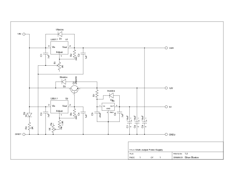
Click the schematic for a scalable PDF version. The source schematic is available in the mercurial repository.
As can be seen from the schematic, the supply design is minimal. The 1N4004 diodes reverse-biased across the regulator devices serve to protect the regulators in the event of inductive kickback or capacitor discharge when power is removed. The 10µF capacitors on each output line may be replaced with larger filters, or augmented with additional bypass capacitors if desired. I would not recommend using smaller filters.
R1 and R4 are the adjustments for the variable and 12V outputs, respectively. R1 is intended to be mounted on the front panel, and a 5KΩ potentiometer or rheostat will provide the full 1.25-30V range of the LM317 (provided your unregulated input is high enough). R4 is a trimmer, used to adjust the 12V output to the value required to provide 12V (or 13.8V, or whatever your usage requires) on the high current output. An LM317 is used in this position not only to allow for outputs slightly greater than 12V (as "12 volt" supplies are commonly truly lead acid battery replacements), but also to compensate for the base-emitter drop across the 2N3055 pass transistor.
R7 is optional, and serves to drop the input voltage to the 7805 under load, distributing dissipation. Any suitably low-resistance high-wattage resistors may be inserted here, provided that the voltage drop at 1.5A does not cause the input to the 7805 to fall below 7V.
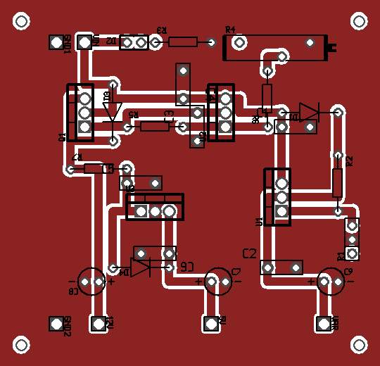
Click the image for a printable layout. The complete artwork for this PCB is available in the mercurial repository.
Note that the source PCB has the copper on the component side of the board, but you will probably want to etch it on the solder side, since the components are through-hole. Drill holes are all 40 mils or larger. The corner mounting holes are sized for 4-40 screws. The completed board fits nicely in a Radio Shack aluminum project box, leaving plenty of room for plugs, fusing, etc.
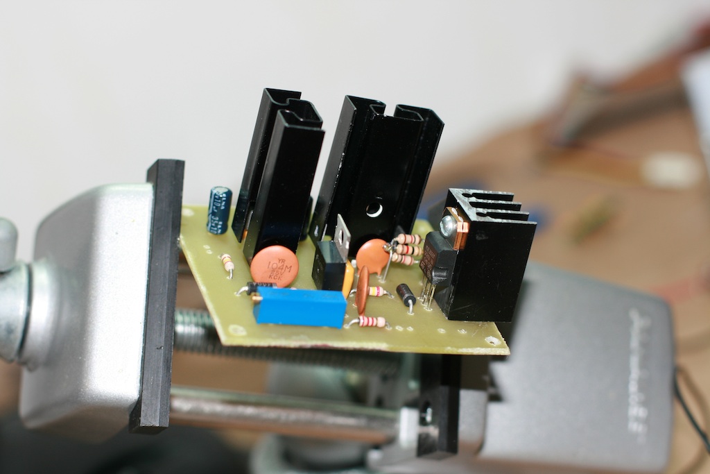
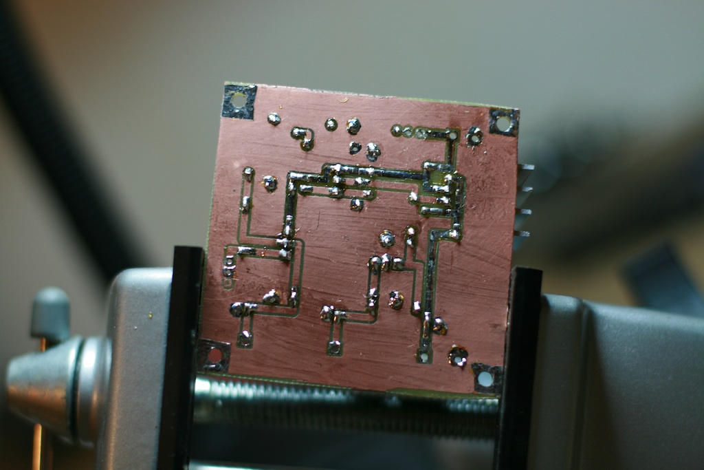
Below are images of the first build of this supply.
Questions? Comments? Contact me at elb@kb8ojh.net and let me know!
 This work by
Ethan Blanton
is licensed under a
Creative
Commons Attribution-NonCommercial-ShareAlike 4.0 International
License. Based on a work from
kb8ojh.net.
This work by
Ethan Blanton
is licensed under a
Creative
Commons Attribution-NonCommercial-ShareAlike 4.0 International
License. Based on a work from
kb8ojh.net.