The Michiana Amateur Radio Club (MARC) Builders' Group met on April 25, 2015 to build an RF noise generator. Some information about the meeting and project appears here.
The noise generator
The noise generator we built is a modification of this noise generator from EEWeb, which was originally published in Silicon Chip magazine, in the January 2005 issue. It appears to have been on page 92 of the print copy, but I do not have access to the original article.
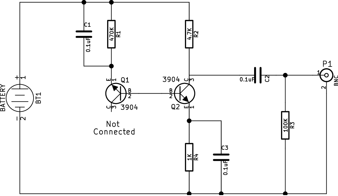
Figure 1. Schematic for the noise generator. The KiCad schematic source file is here.
Figure 1 shows the schematic for the project we built. It differs from the original schematic in minor ways to account for its use at RF and with a 9V power source. (We built it to run from a 9V battery.)
Theory of operation
Transistor Q1 is the noise source in this circuit. Its base-emitter junction is reverse-biased with a tiny current flow through R1, causing it to go into Zener breakdown. This produces broad spectrum white noise, with the usable amplitude falling off as the frequency rises due to junction capacitance in the device. C1 provides a bypass for the very high impedance R1, allowing the noise to be of higher amplitude than the bias current would otherwise allow.
The noise emitted from Q1 is amplified by Q2 and the amplified signal is taken from the collector of Q2 via C2. Q2 is biased for about a 5x DC current gain through R2 and R4, but R4 is bypassed by C3 to allow higher gain at RF. R3 terminates the output when the output is left open; its value is not critical, but should be higher than your expected termination.
Construction
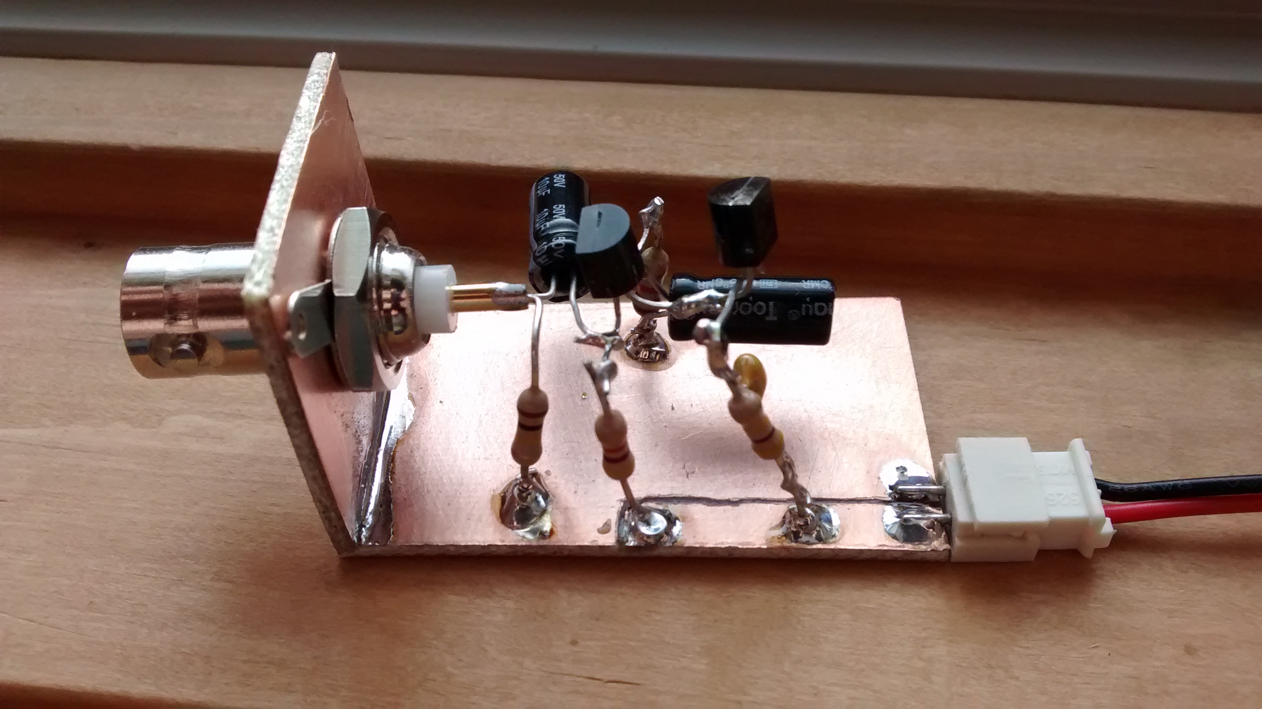
Figure 2. First prototype of the noise generator. Note that the components are high off the circuit board, an undesirable feature at RF.
We chose to construct the devices in “ugly” fashion over copper clad circuit board. Two pieces of copper clad were soldered together perpendicular to each other, forming an “L“ about 2" on the long side and 1" on the short side, by about 1" wide. A BNC connector was mounted on the short side, with the circuit constructed over the long side. Figure 2 shows an example build. Note that it does not use particularly good RF construction techniques, and its bandwidth is somewhat limited by this shortcoming.
This construction technique allowed participants to experience chassis building and rapid prototyping without a fabricated PCB, both skills that can help get a project from a magazine or off the Internet off the ground in rapid order.
Lessons learned
Because we built many units in parallel and tested them on site with a spectrum analyzer, we were able to observe widely varying performance between the units, and account for at least some of it. Construction technique (keeping the components low to the circuit board, leads short, etc.) was measured to account for a variation in high frequency rolloff of at least 10% and maybe more. Individual device characteristics also appeared to play a significant role, with two of the units producing noise out to about 10 times the frequency of most of the other units (300–500 MHz versus 30–50 MHz)!
The event
The event itself was held in my workshop on a Saturday afternoon. We didn't take attendance, but believe that 19 people showed up, including 11 builders and 8 Elmers. Nine projects were built, as two were each built by a pair of builders. Two of our builders were youth, which was great to see! Every project worked by the end of the afternoon, and everyone appeared to have a great time.
Several of the builders had never soldered before, so we spent a few minutes at the beginning of the meeting talking about soldering equipment and important techniques such as keeping things clean, avoiding cold solder joints, and holding the work steady. Two builders brought their own soldering stations and four additional stations were provided by Elmers, so six projects could be soldered at once. This, and space, were a bit of a bottleneck (my shop is only about 20 by 20 feet and is already cluttered around the edges), so for future builds we may have to find a different space or find a way to use the shop more effectively.
All in all, the event was a great success.
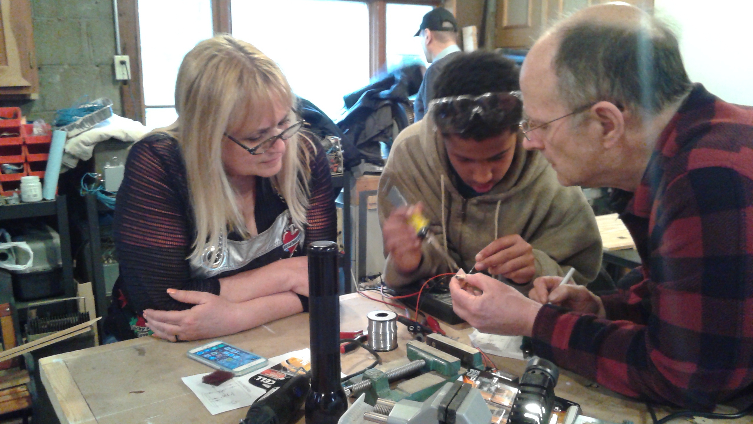
Carol (AC9KF) and Trey build a generator while Harry (KC9EOT) provides some guidance. Photo courtesy of Mike Ciesiolka (KO9Q).
Publication materials
The handout from the session is available here, and it contains the schematic as built and some information about the components used.
The article submitted to the MARC SPARKS newsletter for May 2015 is available here.
