A local ham has recently given me a number of vintage receivers from the 40s and 50s in various conditions from "basket case" to "probably works fine." I'm very excited to sort them out and get them fired up, but I was limited by a practical concern: much tube-type vintage equipment before the late 50s to early 60s has high impedance audio output, and I have only low impedance communications speakers! So I went to Radio Shack and picked up a small audio impedance transformer (1 kΩ center tapped to 8 Ω), then rummaged around in the junk box for parts to complete an impedance adapter board. Figure 1 shows the transformer and found parts alongside the drilled copper clad that will become the adapter.
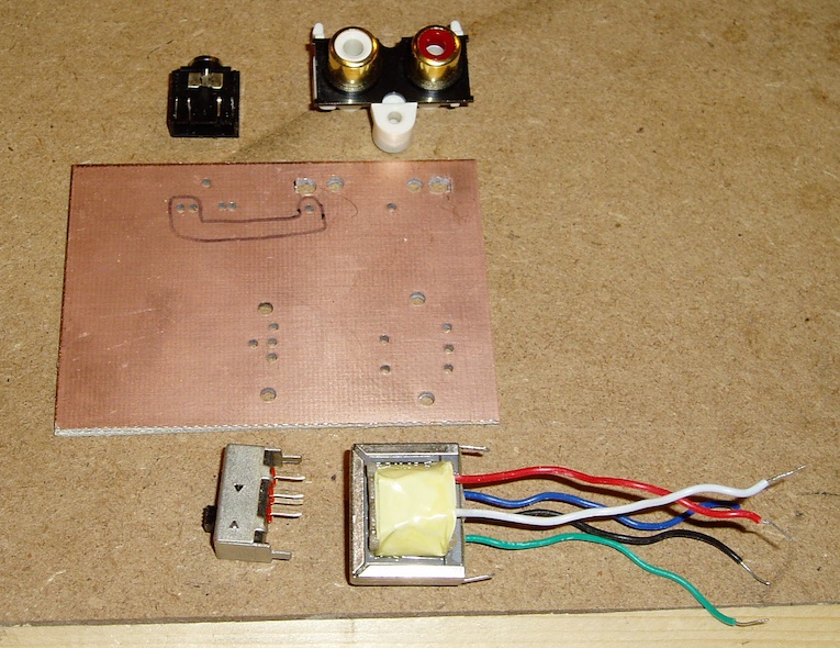
Figure 1. Parts prior to assembly, with drilled copper clad. Markings on the board were to gauge clearance for traces.
While most of the equipment I have right now has an output in the neighborhood of 500 Ω, I decided to take advantage of the 1 kΩ center tapped transformer to provide a switchable 1 kΩ and 500 Ω adapter, so I added a slide switch into the mix. The input side of the transformer is hooked to a phono jack via the switch, and the output side goes to another phono jack and a phone jack in parallel. I considered adding screw terminals to the input and output, but decided that an appropriate phono adapter cable was a faster and easier plan.
As this is a one-off project, and one using found parts for which I do not necessarily have footprints, to boot, I chose to cut the circuit into a piece of copper clad using a Dremel tool. First I marked the copper clad for the found parts, and then I drilled through holes with a drill press. Each through hole was sized by placing drill bits against the lead or mounting tab, and identifying the smallest bit that provided clearance for the lead or tab. For the mounting tabs on the dual phono jack, which had plastic compression clips, I used a small square jeweler's file to square the outside corners of the mounting holes drilled in the press. The squared corners of these holes are visible in the top right of Figure 1.

Figure 2. Top side of copper clad, with clearances for un-insulated through-hole leads.
Since the copper clad I had on hand was double-sided, I had to clear the copper in the vicinity of components with un-insulated through terminals on the top side of the board. Figure 2 shows the top side of the board with these clearances scraped clean by a small sanding drum mounted in the drill press. This isn't the prettiest method of clearing copper, but it is effective. A less aggressive sanding drum would leave a more attractive surface with cleaner edges.
With the top side of the board finished, it was time to cut the circuit traces into the bottom of the board. I didn't draw the circuit on the board before cutting, and as a result, I made a number of cutting errors. I highly recommend drawing your layout on the board with a sharpie before cutting to avoid this — a lesson I've been taught several times, apparently without learning it! Fortunately, for this style of construction the "pads" are large and easy to work with, so fixing errors with hookup or signal wire is trivial.

Figure 3. Bottom of the copper clad, with traces cut in the copper. There are several layout errors on this board that were later fixed with insulated wire (for signal paths) and clipped component leads (for ground paths).
Figure 3 shows the solder side of the copper clad, with traces cut. Note that the fixed switch pole is not attached to the input phono jack center pin (you can see that I initially mistakenly attached it to the output center pins!), and that the two output jack ground pins were mistakenly isolated. These are the errors mentioned above, and they were corrected after the fact with soldered-on wires. The insulation paths were cut using a 1" diameter, thin cutting wheel in the Dremel, which eases the cutting of reasonably straight paths but tends to encourage overrun on outside corners. Cutting wheels also dig deep if you lose concentration or your hand is not steady, so I wouldn't recommend them for very thin board material. Both of these effects are visible on the cut board. Since the transformer leads are insulated, no cutting was required for their placement.
As with most home PCB fabrication, it is essential to examine the board carefully for incompletely isolated traces. This board was isolated on the first try, but a few suspicious copper remnants were left in places, and I scraped them clean with a utility knife. Solder flow can easily bridge otherwise disconnected traces if a hair of copper is almost crossing an insulation gap, so it's best to clean them up before soldering.
The final product is depicted in Figure 4. A couple of quick plugs later, and the crackles of a Hallicrafters SX-25 came out of my 8 Ω communications speaker as the tubes warmed up!
An additional advantage of an adapter like this, particularly for use with headphones, is DC output isolation. It is not unheard of for vintage equipment to have a B+ offset voltage across the output terminals, and with vintage homebrew projects it is even somewhat common. As these B+ voltages normally range from 150 to 300 volts in receive circuits, it is essential that they are isolated from speakers and headphones that might come in contact with the listener. I had originally intended to provide pass-through impedance setting on the three-position slide switch, but ultimately decided not to in order to address this B+ voltage concern. The third position is therefore ground, and simply shorts the output jacks while leaving the transformer output floating.
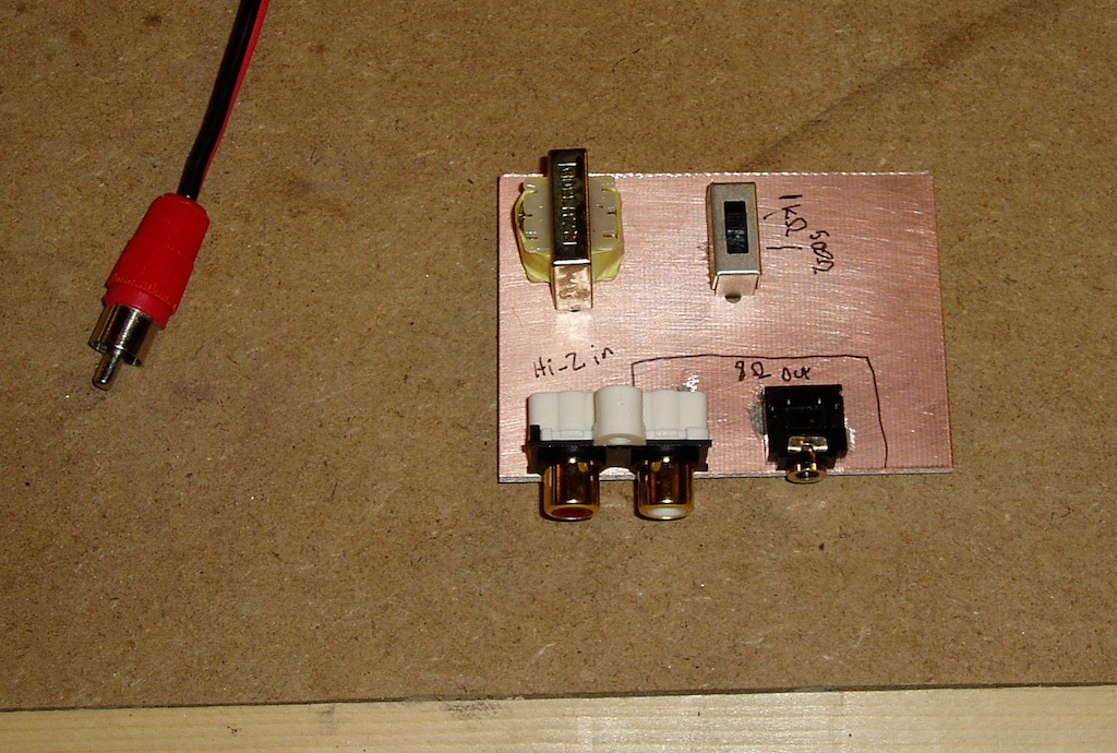
Figure 4. The finished adapter, with sophisticated Sharpie labeling.
